一,English Technical Specification Table
Category Specification Details
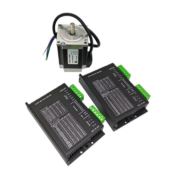
Product Model DM542 (IO Pulse Control Version)
Drive Type Digital 2-phase hybrid stepper driver, open-loop control
Compatible Motors 2/4/8-wire 2-phase hybrid stepper motors (NEMA17/23/24, 57/86mm flange)
Input Voltage DC 18–50V (recommended 24–36V)
Output Current (Peak) 1.0–4.2A (8-level adjustable via DIP switches)
Logic Voltage 5V/24V (optically isolated input)
Max Pulse Frequency 200kHz (up to 500kHz optional)
Control Modes Step & Direction (PUL/DIR) or CW/CCW (double pulse)
Microstep Resolution 15/16 levels (200–25600 steps/rev, up to 51200 steps/rev via software)
Core Technologies 32-bit DSP control, auto-tuning, anti-resonance, sine-wave microstepping
Protection Functions Overvoltage, undervoltage, overcurrent, overheating, motor short-circuit protection
Idle Current Function 50%/90% of dynamic current (selectable via SW4)
Dimensions (L×W×H) 118×75.5×25.5mm (typical) / 118×75×32mm (variant)
Operating Temperature 0°C–50°C
Storage Temperature -20°C–65°C
Humidity Range 40%RH–90%RH (non-condensing)
Certifications CE, ROHS compliant
Typical Applications CNC routers, laser cutters, labeling machines, packaging equipment, 3C assembly lines, engraving machines
二,Wiring Guide
1. Interface Definition
Terminal Name Function Description
DC+ Positive pole of DC power supply (18–50V)
DC- Negative pole of DC power supply (ground)
A+/A- Motor phase A coil connections (polarity-sensitive, avoid miswiring)
B+/B- Motor phase B coil connections (polarity-sensitive, avoid miswiring)
PUL+ Positive terminal of pulse control signal (optically isolated)
PUL- Negative terminal of pulse control signal (optically isolated)
DIR+ Positive terminal of direction control signal (optically isolated)
DIR- Negative terminal of direction control signal (optically isolated)
ENA+ Positive terminal of enable signal (high level enabled; floating = enabled)
ENA- Negative terminal of enable signal (low level disabled)
ALM Alarm output (active when fault occurs: overvoltage/overcurrent/overheating)
2. Wiring Methods
Power Wiring
- Use non-regulated DC power supply (recommended) or regulated switching power supply (set to max output current).
- Ensure correct polarity of DC+ and DC-; reverse connection will damage the driver.
- For multiple drivers, connect power in parallel at the power supply end (avoid daisy-chain connection).
(2)Motor Wiring
- Connect motor A-phase coil to A+/A-, B-phase coil to B+/B- (match motor wiring diagram).
- Do not connect motor wires to power terminals; avoid short-circuit between motor phases.
- Do not hot-plug motor connectors when powered on (high induced voltage may damage the driver).
(3)Control Signal Wiring
- Common Anode Connection: Connect PUL+/DIR+/ENA+ to controller's signal output; PUL-/DIR-/ENA- to controller's GND.
- Common Cathode Connection: Connect PUL-/DIR-/ENA- to controller's signal output; PUL+/DIR+/ENA+ to controller's VCC (4.5–28V).
- Use shielded cables for control signals (single-end grounding at controller side, 10cm+ distance from motor wires to avoid interference).
3. 接线注意事项(Wiring Notes)
- All wire ends must not be exposed outside terminals (prevent short-circuit).
- Do not solder wire ends before inserting into terminals (avoid overheating and poor contact).
- Tighten terminal screws firmly to prevent loose connections and abnormal heating.
三,DIP Switch Settings
1. Switch Position Definition
Switch Group Function
SW1–SW3 Dynamic current adjustment (peak current)
SW4 Idle current mode / Auto-tuning function
SW5–SW8 Microstep resolution adjustment
2. 电流设置(Current Setting - SW1–SW3)
Peak Current RMS Current SW1 SW2 SW3
1.0A 0.71A ON ON ON
1.46A 1.04A OFF ON ON
1.92A 1.36A ON OFF ON
2.37A 1.69A OFF OFF ON
2.84A 2.03A ON ON OFF
3.32A 2.36A OFF ON OFF
3.76A 2.69A ON OFF OFF
4.20A 3.00A OFF OFF OFF
3. Idle Current & Auto-Tuning - SW4
Function SW4 State Operation Description
Idle Current (50%) OFF Auto-reduce to 50% of dynamic current after 400ms of pulse stop (reduces heating)
Idle Current (100%) ON Idle current = dynamic current (for high holding torque requirements)
Auto-Tuning Function Toggle Flip SW4 ON↔OFF within 1 second (no pulse input during operation; optimizes motor parameters)
4. Microstep Setting - SW5–SW8
Steps/Rev SW5 SW6 SW7 SW8
400 OFF ON ON ON
800 ON OFF ON ON
1600 OFF OFF ON ON
3200 ON ON OFF ON
6400 OFF ON OFF ON
12800 ON OFF OFF ON
25600 OFF OFF OFF ON
1000 ON ON ON OFF
2000 OFF ON ON OFF
4000 ON OFF ON OFF
5000 OFF OFF ON OFF
8000 ON ON OFF OFF
10000 OFF ON OFF OFF
20000 ON OFF OFF OFF
25000 OFF OFF OFF OFF
5. Setting Notes
- Power off the driver before adjusting DIP switches (settings take effect after power-on).
- Match the set current to the motor's rated current (do not exceed motor maximum current).
- For low-noise and high-precision requirements, select 400 steps/rev or higher microstep resolution.


Product Tags:

|
|
2-Phase Open-loop DM542/DM542-IO Stepper Motor Driver 32-bit DSP 1.0-4.2A DC 24-80V For Nema23 57mm Stepper Motor Images
|


